

PCBTree: A Christmas Tree PCB I Made in High School
By Ian Thompson on Friday, December 1, 2017
A high school trip to Las Vegas might seem unusual, but it sparked my fascination with electronics. Inspired by ElectroBoom's near-death fail compilations, I transitioned from programming to hardware, leading to the creation of PCBTree—a Christmas tree-shaped printed circuit board. Designed using KiCAD and powered by an ATTiny85, this project was my entry into the world of DIY electronics.
I remember our family trip to Las Vegas in high school. You are probably thinking, "Wow, what kind of family brings kids to Las Vegas?" While that is certainly a reasonable question, trust me, it isn't as weird as it sounds.
On this trip, I came across a near death fail comp (must watch) from the many times ElectroBOOM almost killed himself. While these videos are a sure deterrent to fooling around with electricity (and quite shocking!), I grew fascinated by the world of electronics.
You see, I had already been exposed to the world of programming. I knew how to program the computer but didn't know how to make the computer. This spark of interest led me to more and more beginner videos on electronics, and I eventually stumbled upon the Arduino.
I pulled out my Amazon app, ordered a beginner Arduino set, and got to work as soon as I got home from our trip. Months later, PCBTree was born.
Playing around with a shift register.
PCBTree
After fooling around with breadboard circuits, I knew the time had come to get a printed design. Thus, I created PCBTree.
PCBTree is a printed circuit board (PCB) in the shape of a Christmas tree. I designed this board using KiCad, an open-source PCB CAD tool. I designed the board cutout and laid each trace by hand.
The board is powered by a 5V DC power brick. This powers each of the green and red LEDs on the board. The green and red LEDs are on different circuits, each connected to a transistor, which is then connected to an ATTiny85 microcontroller.
This ATTiny85 runs a simple C program that reads data from the connected trim potentiometer. This potentiometer increases the blinking speed, alternating between the red and green LEDs. A pot value of 0 turns off all the LEDs, and a pot value of 100 makes the LEDs shine steadily.
Each of the LEDs, resistors, transistors and ATTiny85s are surface-mounted to the PCB (yes, this was a pain in the butt to do as an inexperienced solder-er and with highly unprofessional equipment). I then created a simple mount to hot glue the PCB on out of some spare wood in my dad's shop.
Conclusion
I wish I had more details on the build process for this project. As you have read by the warning placed at the top of this post, I am writing this retroactively, recalling years-old memories.
You can view this project in the following GitHub repo:
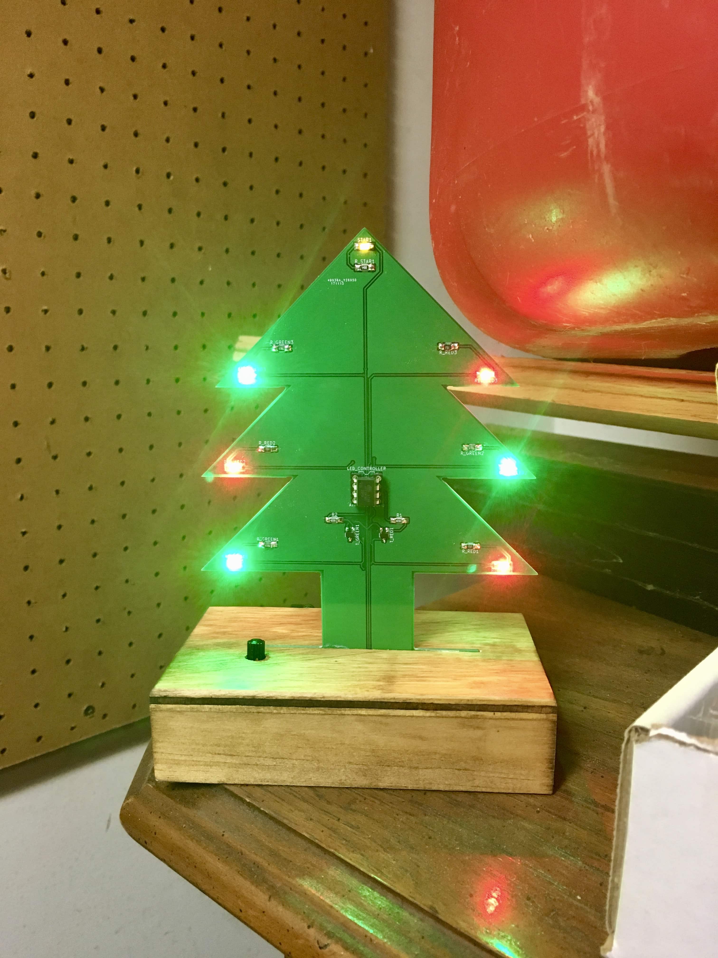
Individual PCBTree on wooden mount.
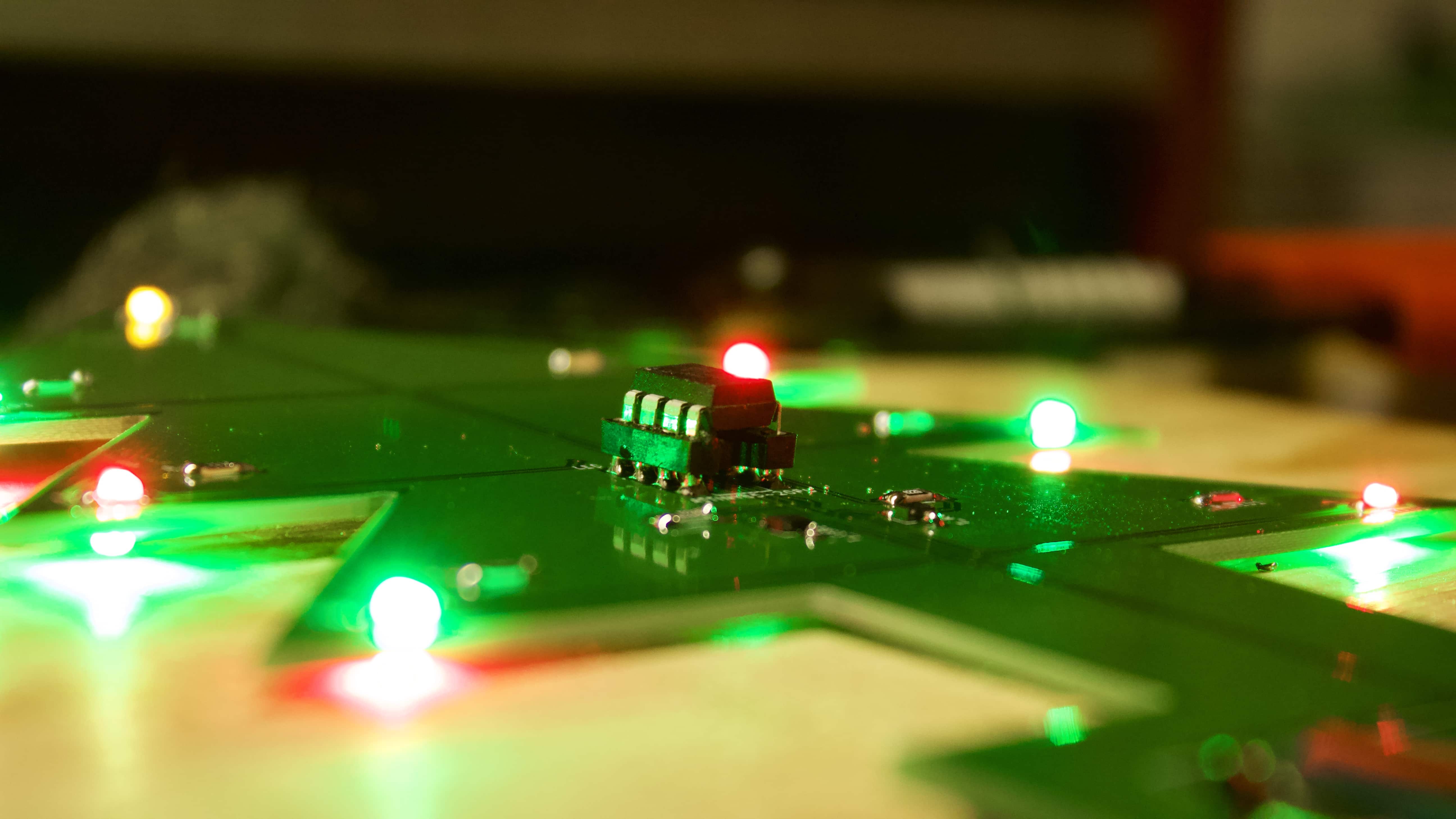
A style shot of PCBTree
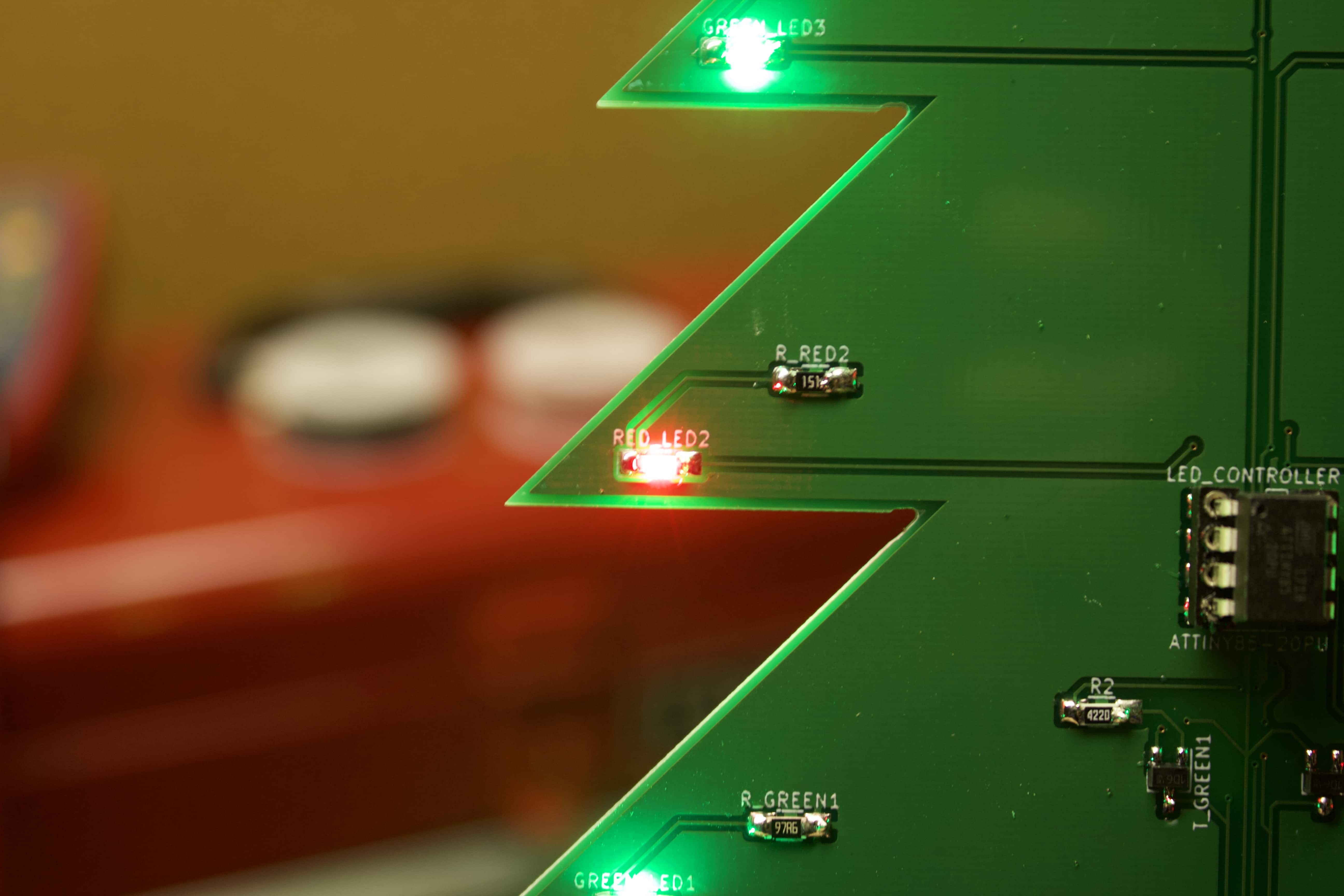
Close-up of green and red LEDs.
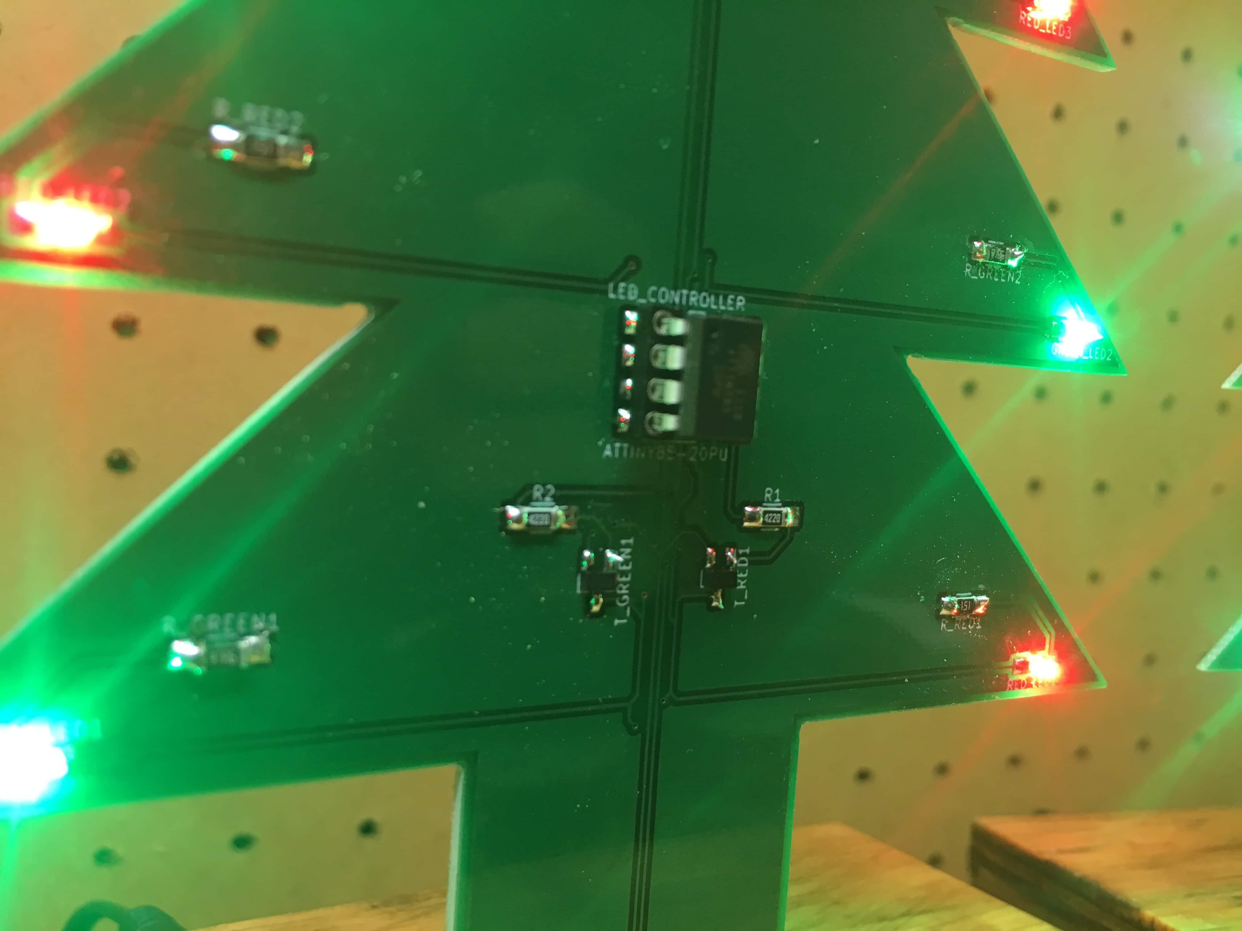
Close up of ATTiny85 and transistors.
* This post may contain affiliate marketing links. By clicking these links, a portion of money you spend on the websites you are referred to may be shared with the owner of this site.